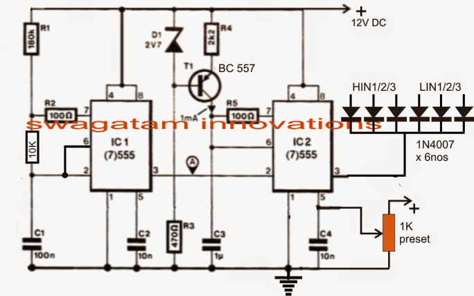
3 Phase Vfd Wiring Diagram

Vt Commodore Ignition Wiring Diagram, Complete Wiring Diagrams For Holden Commodore VT, VX, VY, VZ, VE, VF, 5.36 MB, 03:54, 32,796, John Amahle, 2018-08-01T19:37:41.000000Z, 19, Vt Commodore Ignition Wiring Diagram, to-ja-to-ty-to-my-to-nasz-swiat.blogspot.com, 1272 x 1800, jpeg, bcm pcm 12j swiat nasz, 20, vt-commodore-ignition-wiring-diagram, Anime Arts
Vfd control wiring with diagram | vfd wiring diagram | vfd motor control wiringin this video you will learn about vfd control wiring with diagram | vfd wirin. Vfd circuit diagram variable frequency schematic drive drives ac wiring bradley allen motor output 1336 circuits solid components filter block. 1 hp (0. 75 kw) single phase output vfd | gohz. com www. gohz. com. Phase vfd single motor wiring output hp induction run capacitor kw instruction.
Vfd start stop wiring diagram electrical4u how to make a 3 phase circuit homemade projects plc skills hands on electrical training amatrol visio d0043 apollo vsd basics controls the motor running variable frequency drive metso schematic typical scientific control of induction using and vfds probotix wiki controlling with manual inputs technical. A wiring diagram is a streamlined traditional pictorial representation of an electrical circuit. Enclosure fan2 on 30hp, 40hp, and 100hp at 480v. Make sure that the voltage you will be. Homepage / 3 phase vfd wiring diagram. 3 phase vfd wiring diagram. 3 phase vfd wiring diagram. By facybulka posted on august 20, 2017. The most common use of 3 wire control is a startstop control.
3 phase VFD manual | Circuit projects, Circuit diagram, Circuit

How to Make a 3 Phase VFD Circuit | Homemade Circuit Projects | Circuit projects, Electronic

44 3 Phase Vfd Circuit Diagram - Wiring Diagram Source Online
Controlling 3-Phase Induction Motors Using VFD And PLC
3 Phase Induction Motor Driver Vfd Motor Control Circuit Diagram Pdf - kasiadorota

How to handle imbalances from light loads on VFDs

How to Build a 3 Phase VFD Circuit

Industry Automation Blog: How to wire 3 phase motor to VFD

Vfd Control Wiring Schematics | Wire

